
Great story, shame he wouldn't share his rigs though !!
Posts by smfelton
-
-
Haha welcome back!!
-
Nice......Well done !!
-
Hello and welcome !
-
Welcome !!
-
Welcome along !!
-
Welcome, i'm sure you will fit right in !!
-
I hadn't thought about the NeoPixels, but I have now, and just ordered some clones.
-
Shane: your modifications to Daltona's original design pretty much nails everything I need out of my controller bar a couple of tweaks. What do you think about adding another 14 segment display to show the current performance name next to the existing rig name display? I'd plan to use the Arduino mega so there should be enough spare serial connections to add one without too much hassle. The only other thing I might do is add some kind of indication to the stomp and X buttons to show which type of effect is loaded to each slot. The colour LED method the KPA controller uses seems sensible and could be achieved using some three colour RGB LED's. This would mean some more shift registers (2 extra I think) but should be achievable. I could take it to the extreme and try for an LCD above each stomp and performance slot to display rig and stomp info like the Liquid Foot does, but its probably beyond my abilities and I'm not sure the Arduino could cope with all those displays.
Hi, i'm using a Mega, just a cheap clone off ebay, it works fine but may account for the differences. All of my 'stomp' and 'fx' leds are RGB, and that is an upgrade I intend to do eventually to give the correct colours, I already have the circuit breadboarded and the code for this is in mortl's sketch. The performance name is shown in the 14 seg display until the patch is selected, which is enough for me. But it would not be too hard to add another. I have looked putting at a small lcd above each stomp using nokia 5110 display which are very cheap and easily available. That again is an option I may add later. I was completely new to Arduino when I started this so it's been a steep learning curve, and the current controller I have was more about learning than giving me my final controller.
I've added my latest iteration of the code, still very much work in progress.
-
After days of banging my head I've finally got the LEDs working in browse mode, just the performance mode to do now, I'll upload the updated sketch later. For anyone trying themselves the problem was the spi mode, for some reason it needed to be 0 not 1.
-
Great stuff, love it. Great fun, great sound and well shot video. When will us independent underdogs of the music industry get our day. Great songs like this just do not get the audience they deserve. Well done to you all.
-
I've updated the Arduino Sketch attached above, to make sure it gives correct credit to the original author.
-
Thanks for that mortl, i'm actually using daltona's sketch and circuit, this uses 2 x 75HC595 shift registers for the leds, my original build was based on your code but I really liked the displays and the configuration menu in dortl's. I tried combining the code but it was just too much work for me, so i'm having to use his code and modifying for my needs.
Thanks again for your help though. -
If anyone is wondering the box is a steel oil drip tray from ebay, this guy makes them any size you want.
http://www.ebay.co.uk/itm/1116…geName=STRK%3AMEBIDX%3AIT -
Hi, I know this thread is quite old but I have used all the hard work done here to build my own board. I'm using 21 buttons and two expression pedals and an Arduino Mega serial port 3 for the midi.
The whole thing runs on a Cat6 cable to an ethercon connector supplying midi and power. I have got all the buttons working and added some basic looper functions (still needs work). I am having a huge problem with understanding the leds and how they are wired and programed. I have stuck to 16 leds which keeps it at 2 595s but the mapping is really confusing me. Firstly there are 16 leds in the circuit but only 15 on the board, so "which one/end is missing ?" Also the diagram shows pin7 of the first 595 wired to pin 14 of the second, everything I have read shows it should be pin 9 to 14. So any explanations and help would be fantastic. I have attached my code/sketch for anyone to play with, but the led masks are wrong so definitely need changing.
Here are some pictures.[Blocked Image: http://s3.postimg.org/k8p0nq49f/Photo_18_06_2015_14_48_49.jpg]
[Blocked Image: http://s9.postimg.org/gs8den79r/Photo_18_06_2015_14_49_04.jpg]
[Blocked Image: http://s22.postimg.org/vciliwh29/Photo_18_06_2015_14_49_10.jpg]
[Blocked Image: http://s3.postimg.org/7eqyudqtv/Photo_18_06_2015_14_49_16.jpg] -
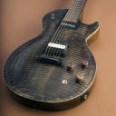
My competition prize arrived today
 i'm very happy !!!!!! It looks fantastic !!!
[Blocked Image: http://s10.postimg.org/7m0wkw3qx/Photo_05_06_2015_13_24_51.jpg]
-
Great thank you
-
It's coming along quite nicely, having to teach myself the Arduino as I go. Another question, what pins is your TLC5940 connected to, SCLK, Blank etc. Thanks again.
Shane -
Looks fantastic, can't wait to get it. Does it come with the Croc ?

-
Loving it !!!!