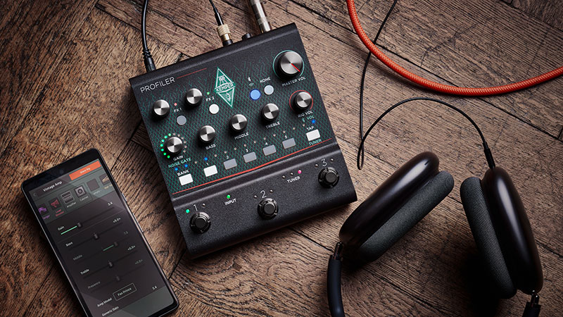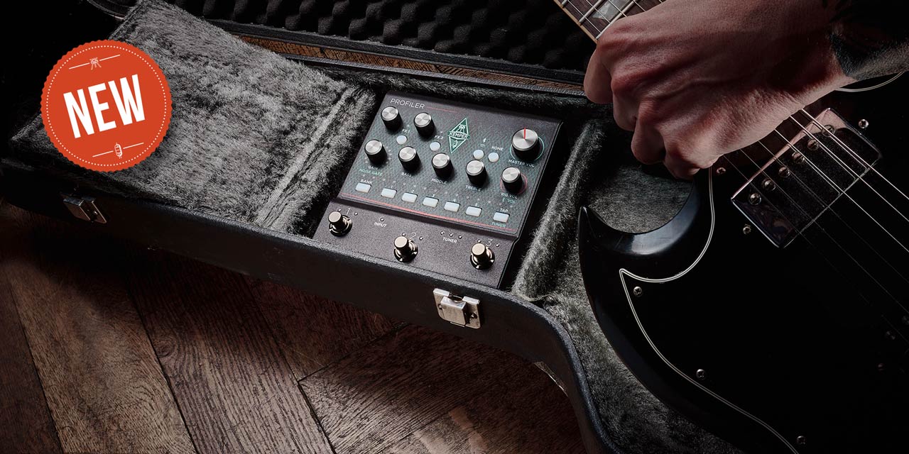
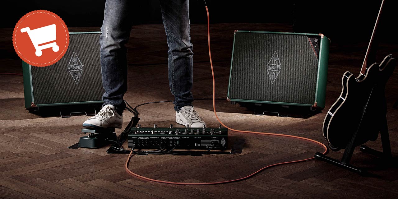
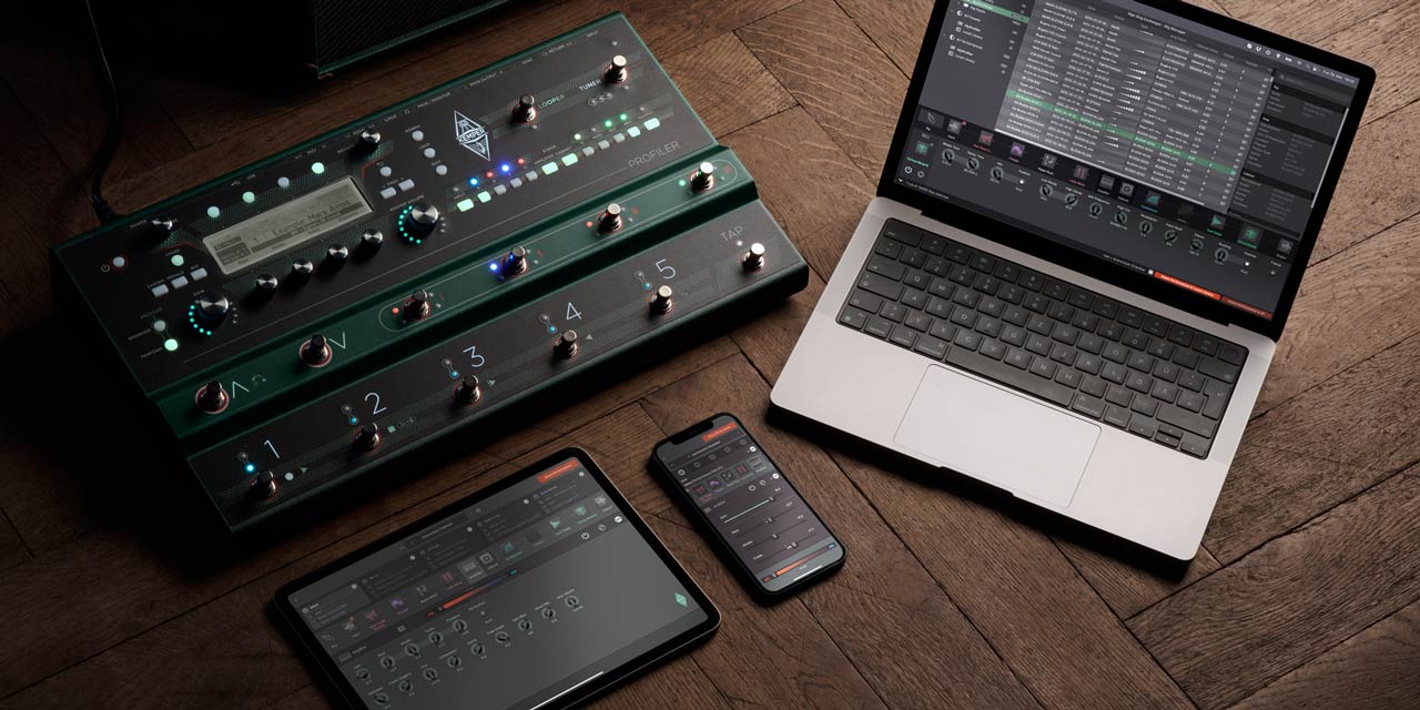
PROFILER Player - available now!
The most complete serving of professional amp tones and studio-grade FX per footprint
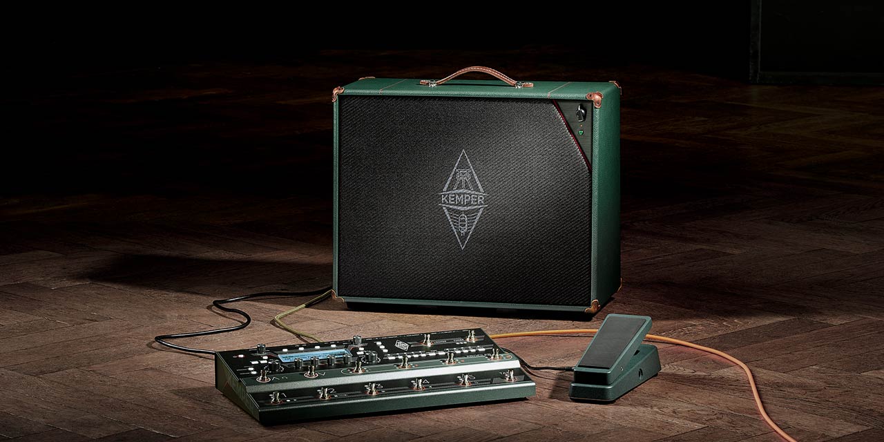
KEMPER Power Kabinet
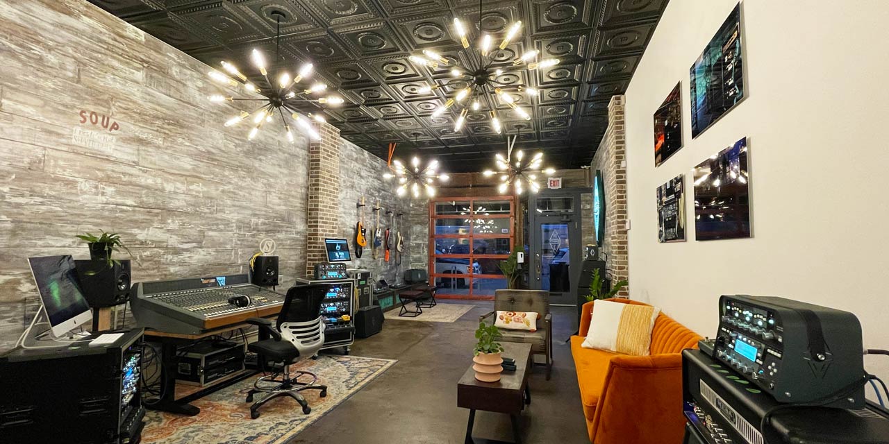
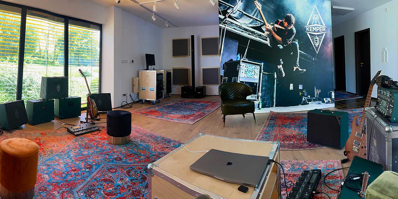
KEMPER Showroom Chicago (USA)
Get your personal PROFILER demo and training! By appointment only.
Select your location to view local content and shop our online store: